Red vs. Blue - Networking Explained
- 13 minsHello! Welcome to my third installment of Red vs. Blue content. This post will aim to explain the concepts and developments of the networking infrastructure behind our Red vs. Blue project.
Quick refresher on Red vs. Blue
Red vs. Blue, or RvB, is our college organization’s twist on the CCDC format. Teams of 4 are placed into a vulnerable environment and given a unique experience of troubleshooting, responding to incidents, and completing business objectives against an active red team.
Preparation and development of Red vs. Blue competition involves few major steps: brainstorming the setting, creating vulnerable machines, configuring the networking, and setting up a scoring engine.
To read more about RvB, check out this blog by CPP SWIFT.
This post builds off of my first RvB post and my second RvB post, so please check those out if you haven’t already.
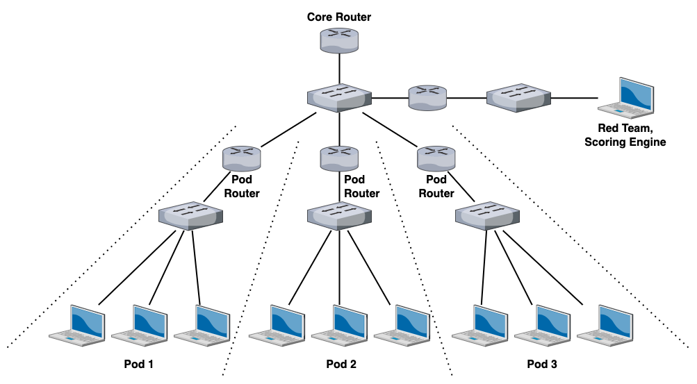
Previous Red vs. Blue networking configuration
This was how RvB was previously setup. After the previous networking guy graduated, this was basically what I was left with in terms of documentation.
Primer to ESXi and vSphere networking
We run RvB mostly off ESXi, which is a Type-1 hypervisor made by VMware. In addition to creating VMs, you can create virtual networks to connect VMs together.
- VMware ESXi allows you to create vSwitches, or virtual switches.
- vSwitches operate pretty much exactly the same as physical switches.
- vSwitches contain port groups, or groups of virtual ports on a vSwitch.
To understand port groups a bit better, imagine you have a super huge, unconfigured virtual switch that contains an absurdly large number of ports.
Chances are, you don’t want all the ports to be configured exactly the same way – you want some ports to be used by Production VMs, some ports to be used by Development VMs, some ports to be used by Engineering VMs, etc.
We can make a port group for each of these:
- a new port group for all production VMs called “Production Port Group”,
- a new port group for all development VMs called “Development Port Group”,
- a new port group for all engineering VMs called “Engineering Port Group”,
- and so on and so forth.
We’ll also assume that all Production VMs are connected to the Production Port Group, all Development VMs are connected to the Development Port Group, and all Engineering VMs are connected to the Engineering Port Group.
We can also create logical rules or policies on each port group. For example, if we want to implement traffic shaping on our Production VMs, we can do so by editing the traffic policies on the Production Port Group without affecting the Development Port Group and the Engineering Port Group.
ESXi port groups are a totally different concept than things like port bonding, port aggregation, etc. If you want to learn more, this article has a good read on vSphere networking.
We must also talk about vmnics. Each of the PowerEdge servers that we were running contained four Ethernet interfaces, which were referred to as “vmnics” in ESXi. Each vmnic interface has its own ID, starting from zero. So if we had four Ethernet interfaces, our vmnics would be labeled as follows:
- vmnic0
- vmnic1
- vmnic2
- vmnic3
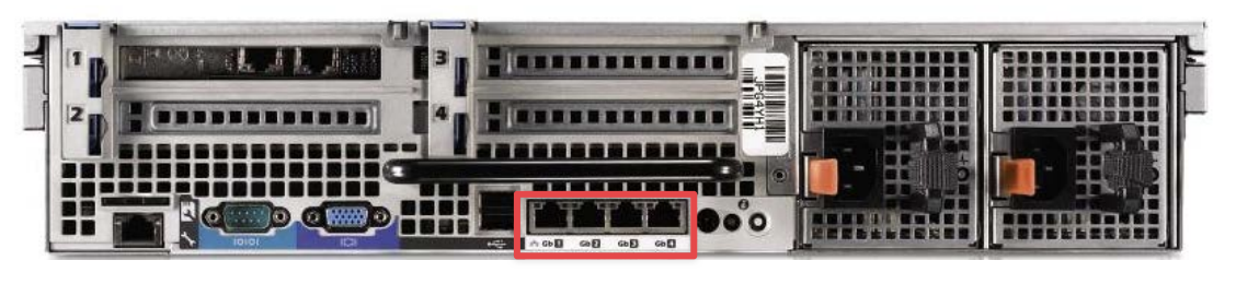
(The Ethernet interfaces illustrated above are called “vmnics” in ESXi language)
1-to-1 NAT
The first thing I focused on was reimplementing the 1-to-1 NAT on the pod pfSense routers. I did not know how to configure 1-to-1 NAT, so I had to consult the pfSense documentation to figure out what was going on.
The goal of 1-to-1 NAT is to get every system on each pod to be individually accessible from the core network (AKA have its own IP address in the core network subnet range, which was 172.16.0.0/16).

After much trial and error, this was the NAT configuration that allowed us to achieve 1-to-1 NAT:
- Under System → Routing, ensure that the default gateway is configured to be the Core Router’s LAN interface (172.16.0.1).
- Under Firewall → Virtual IPs, create a new entry with the following settings:
- Type - Proxy ARP
- Interface - WAN
- Address Type - Network
- Address(es) - 172.16.X.0/24 (X being the team number)
- Under Firewall → NAT, create a new 1-to-1 mapping:
- Interface - WAN
- Address Family - IPv4
- External subnet IP → WAN address
- Internal IP → LAN Net
- Destination - Any
VLANs
VLANs, or virtual LANs, is a feature of switches that allow you to logically separate broadcast domains on a single switch.
Simply put, with a standard switch without VLANs, you can only attach one network onto that switch. If you want to have two separate networks, you would need two separate switches.
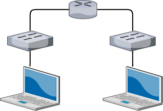
Each network would need to be physically separated with two different physical switches. However, with VLANs, you can attach multiple, logically separated networks on a single switch.
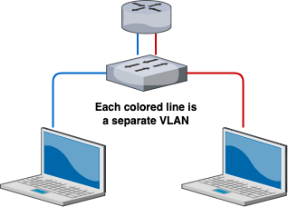
In this example, notice how the number of switches have reduced with the implementation of VLANS. If we wanted to create a three, four, even a hundred separate networks, we can utilize VLANs to do all of that on a single switch.
That’s one of the benefits of VLANs - less infrastructure overhead when creating new networks, and this is the main benefit we’ll focus on in this blog.
Now, how does this relate to vSwitches and ESXi networking? If you recall from in the beginning of the post:
vSwitches operate pretty much exactly the same as physical switches.
If we wanted to create separate, isolated networks on our ESXi instances, then we would need to create separate vSwitches for each network. However, ESXi comes with the amazing ability to configure VLANs on our vSwitches. This means that we can create several separate networks without needing to make new vSwitches.
If we go back to our production/development/engineering port group example, we can configure VLANs on each port group:
- Production Port Group - VLAN 10
- Development Port Group - VLAN 20
- Engineering Port Group - VLAN 30
And this would have the effect of isolating each port group so that the Production VMs are on a separate network from the Development VMs, the Development VMs separate from the Engineering VMs, so on and so forth.
Now with VLANs in mind, let’s go back to RvB networking.
If we refer back to our first RvB topology, you can see that each pod network would require its own vSwitch. The diagram only shows three pod networks, but our RvB can get upwards to 20 teams, which means having to create 20 vSwitches.
This is a lot of unnecessary work and would create a mess of vSwitches and port groups in our ESXi lab.
I wanted to reduce creating new vSwitches whenever possible, so here were the steps I did:
- Remove all the unnecessary vSwitches and just make one vSwitch that will hold all of our networks.
- Create four port groups on the single vSwitch:
- CoreNetwork
- Pod01Network
- Pod02Network
- Pod03Network
- Configure the CoreNetwork to have VLAN 1000,
- Configure Pod01Network to have VLAN 1001,
- Configure Pod02Network to have VLAN 1002,
- Configure Pod03Network to have VLAN 1003,
- etc.
(by the way, I did not need to configure these VLANs with these exact VLAN IDs. I could have made CoreNetwork to be VLAN 50 and Pod01Network to be VLAN 635 and this would still operate the same)
To further explain how this works, let’s look closely at a single pod network with our new VLAN configuration:
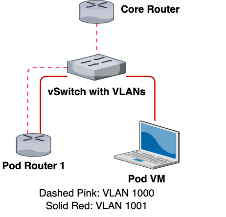
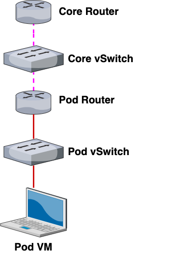
This is what a single pod network would look like with the new VLAN configuration. If we take away the VLAN configurations but retain our same color-coding scheme, this is what the network would look like:
As you can see, by “unwrapping” our VLAN configuration from our network, our topology becomes much easier to understand. Here’s another view that shows the path of an outbound connection from Pod 1’s VM to the Core Router:
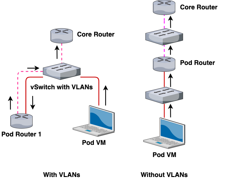
In other words, the interactions and communications between the VMs remain the same and networking works the same as the previous topology. However, with VLANs, we can reduce the number of vSwitches created, reducing our networking overhead on our ESXi instance.
vSphere distributed switches
Sometime later, we had an upgrade to our lab - instead of having individuals ESXi machines, we created an ESXi cluster with vMotion and iSCSI configured to allow for load balancing and other cool VM stuff.
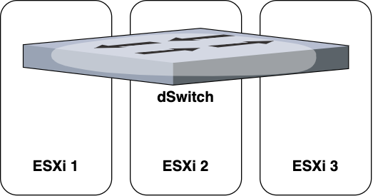
However, now with a vSphere cluster instead of individual ESXis, we had to use distributed switches, or dSwitches for short.
vSwitches and dSwitches do pretty much the same thing, except vSwitches are unique per ESXi, while dSwitches exist for all ESXis in a cluster.
The way that I like to visualize dSwitches is as a very wide switch that spans across all of our ESXi machines:
When we configured dSwitches initially, we were prompted for many other options (such as uplinks, hint hint), which I wasn’t really familiar with so I just skipped those steps.
After creating our dSwitch and configuring our port groups with VLANs similar to what we had above, we expected the networking to work.
However, this wasn’t the case. We had an issue – machines on different ESXis were not able to communicate with each other. This was a huge issue because even though we had clustering enabled, each VM was still “technically” part of an individual ESXi for things like compute power. Also, when creating or cloning VMs, the VM’s host ESXi would automatically be chosen.
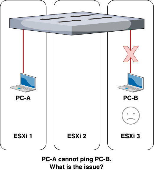
After much troubleshooting, I figured out what the issue was – improper configuration of the uplinks (or lack thereof).
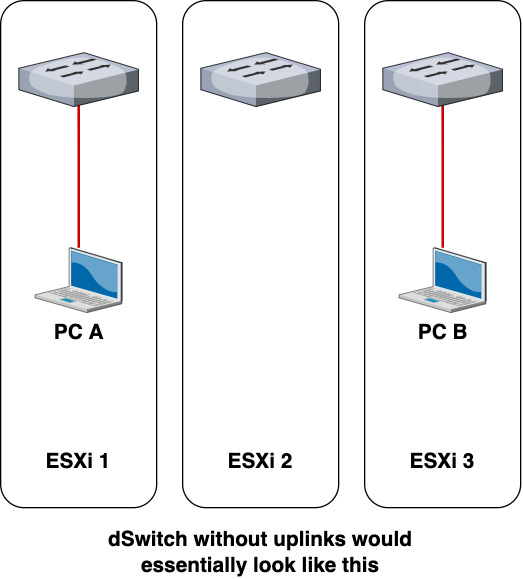
Our dSwitches were configured without any uplinks, preventing each ESXi from being able to communicate any networking information with other ESXis.
Uplinks allow the dSwitch to operate across multiple ESXis. Without the uplink, the dSwitch would still exist across the ESXis (you can still add port groups and connect VMs to those port groups) but each ESXi would treat the dSwitch as their own local vSwitch.
After looking into the VMware documentation, I realized what I needed to do.
I needed to configure the uplinks.
But how? In any normal ESXi setup, configuring uplinks should be relatively straightforward, but with RvB networking in consideration, it became a challenge to figure out what exact settings I needed to put into place.
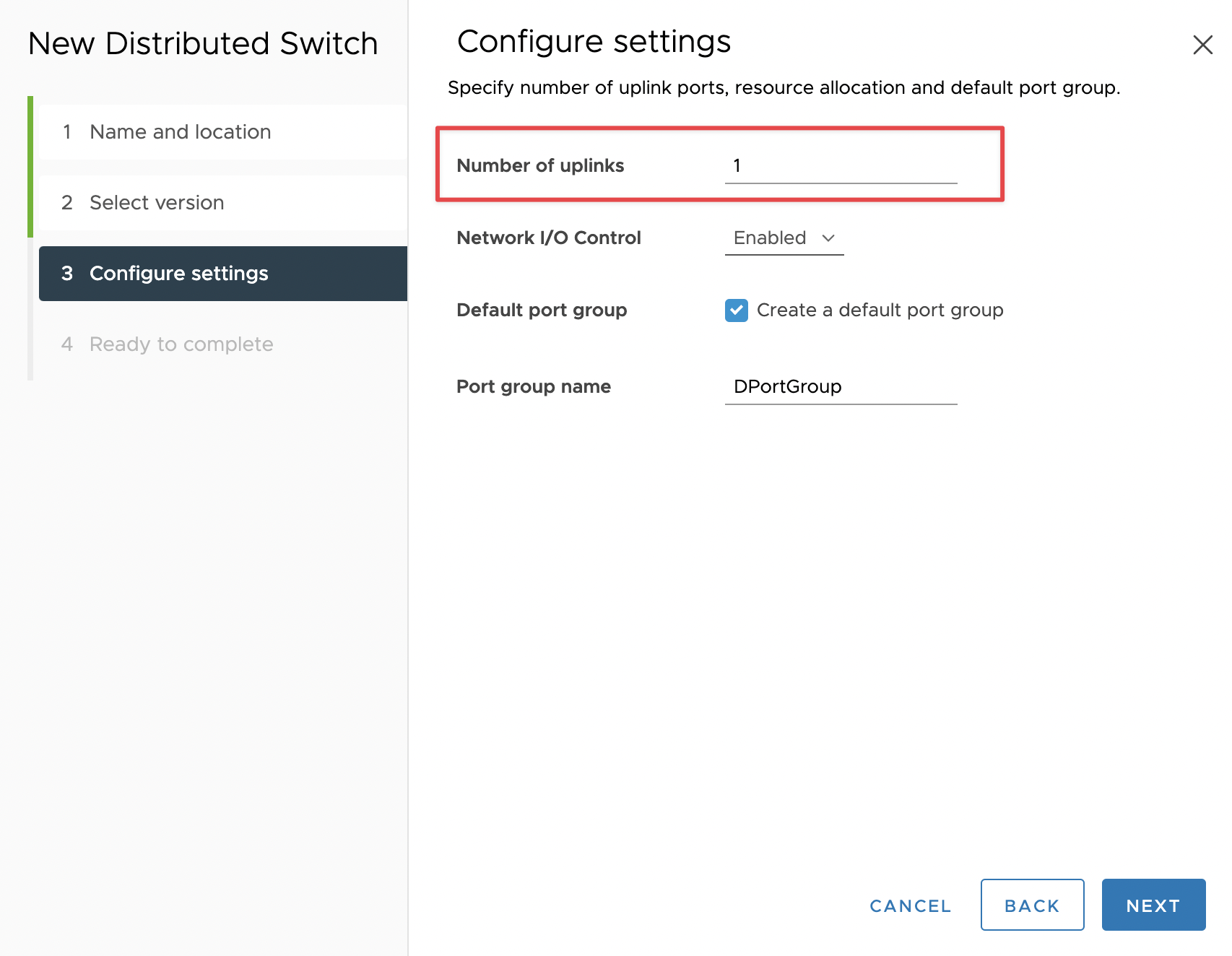
First, I created a new dSwitch with 1 uplink. This setting refers to the number of uplinks per ESXi host, not the total number of uplinks on the dSwitch. Even though I have three ESXis in our environment, I will still need to enter in “1” for the number of uplinks.
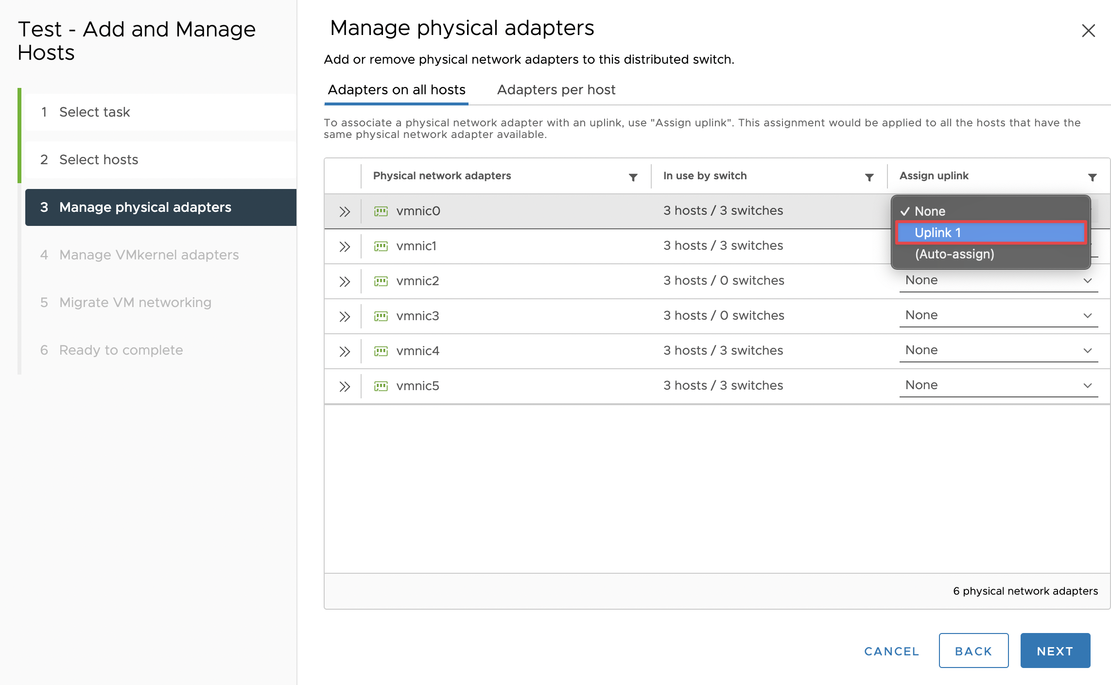
Then I clicked on the “Add and Manage Hosts” setting for the dSwitch, selected all my ESXi hosts to add to the dSwitch, and designated vmnic0 of all my ESXis to be attached to the dSwitch uplinks. After this step, there were extra settings for VMkernels and all that jazz but that’s outside the scope of this post.
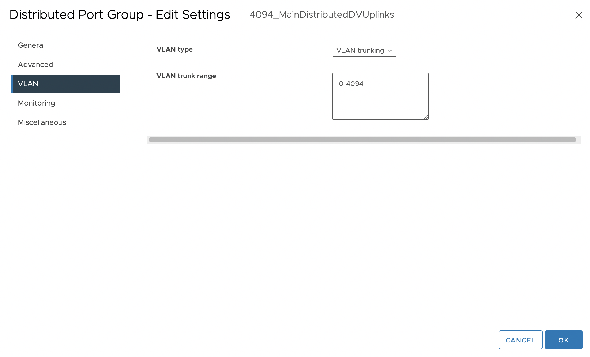
Then I went into the dSwitch’s uplinks’ port groups (which were automatically generated with a dSwitch) and configured VLANs 0-4094 on that port group. (This is ESXi’s way of saying allow all VLANs)
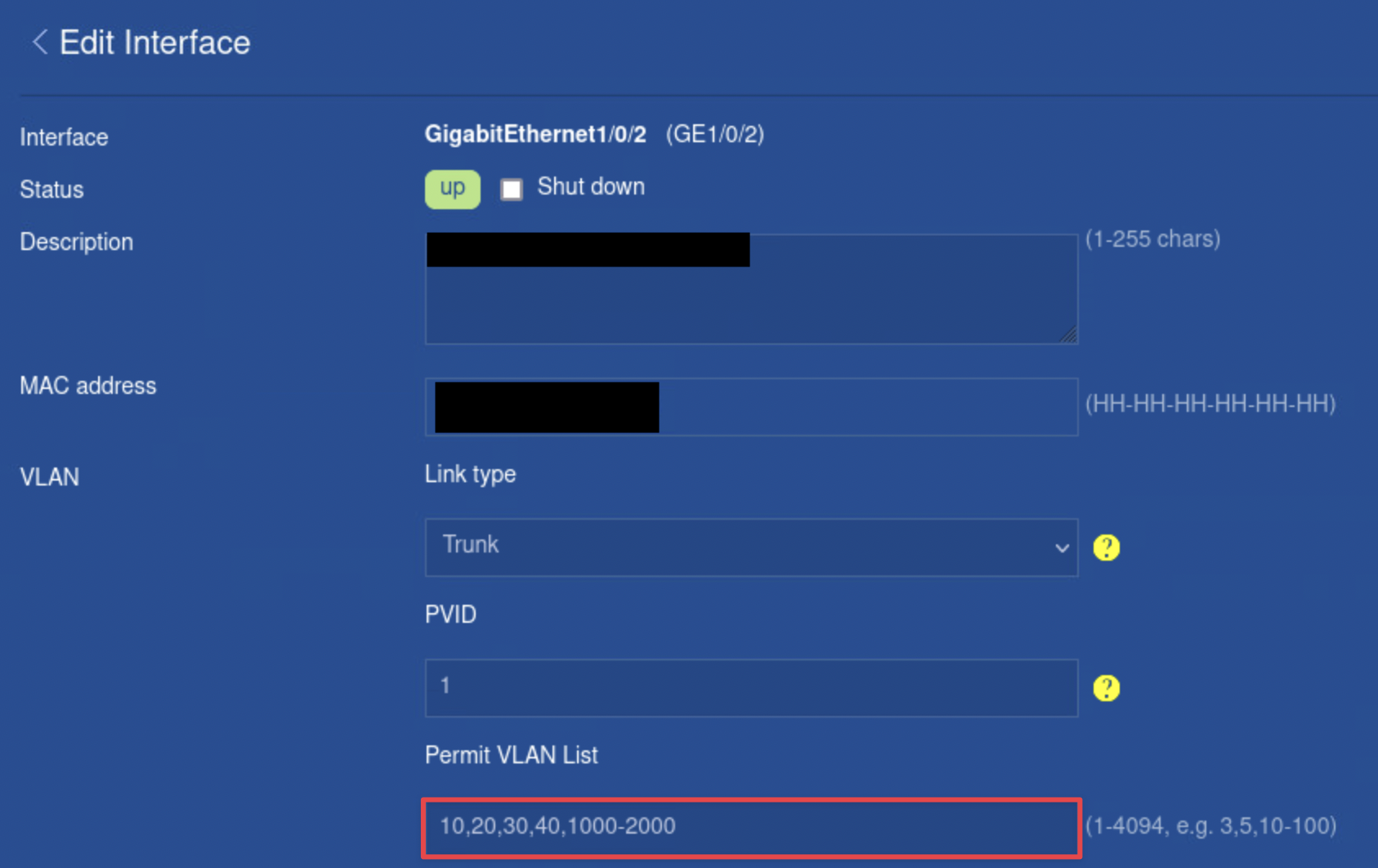
Then I went into the configuration panel for the physical switch that connects all of our ESXis together. I located the specific switchports that were connected to each of the vmnic0’s of the ESXi. I then configured trunking with allowed VLANs 1000-2000 on those specific switchports.
This would allow a user to create a port group with a unique VLAN ID, and be able to have VMs on that port group communicate with each other regardless of which ESXi the VM belonged on. Things like creating VMs, vMotion, and load balancing cause VMs to be automatically placed and migrated in different ESXis, making this configuration an ideal way to create a layer of abstraction from networking at the individual ESXi. In other words, we don’t need to worry about VMs being on different ESXis.
If we took a look at what the topology would look like now, it would look something like this:
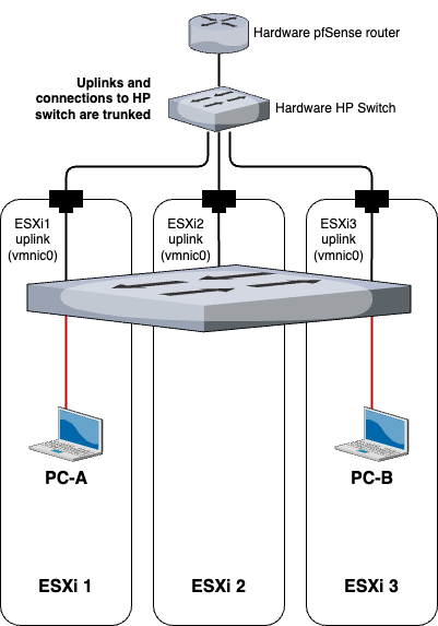
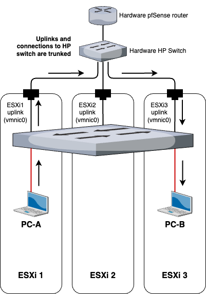
And if PC-A wants to communicate with PC-B, the flow of the traffic would be as such:
Final topology
Now with everything in place, let’s see what our RvB topology looks like now.
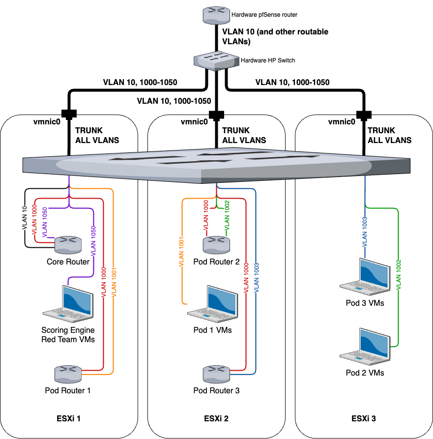
All of the VMs are spread evenly throughout the ESXis to simulate load balancing and automatically migrating VMs across multiple hosts.
Extra thoughts
Overall, I thought it was pretty cool and fun to figure all of this out. It was definitely a challenging project, but really helped reinforce my knowledge of VLANs as well as gain a better understanding of ESXi networking. Each new iteration of RvB networking was like a huge breakthrough for the entire RvB project.
The most difficult part of this project was breaking out of my conventional understanding of networking. Things like vSwitches and dSwitches don’t exactly follow the same rules that you would learn in your typical Cisco or Network+ class. So it was crucial to have an open mind and experiment with many settings as possible and read tons of documentation. Many of the procedures outlined in this post may seem like logical steps that were figured out before performing the actions, but in reality, this was not the case. I would say that 99% of the procedures in this post were discovered through trial and error.
I would also argue that we’ve reached the limits of optimizing RvB networking from an architectural standpoint within the confines of traditional networking. I don’t think there is much else to configure on the switches or routers to make RvB networking, but maybe this opens up the possibility of incorporating software-defined networking (SDN) into RvB as the logical next step.

Taylor Nguyen
Cybersecurity and other stuff